What is Voltage Distortion?
Voltage distortion occurs when an AC output is purely sinusoidal but has small levels of voltage harmonics in addition to the fundamental sinewave frequency. This low level of voltage distortion is often difficult to see on an oscilloscope and requires a power analyzer or harmonics analyzer to quantify. Distortion is typically expressed in percentage (%) of the fundamental, based on the ratio between RMS amplitude of the higher harmonics versus the RMS amplitude of the first harmonic or fundamental (h=1).

The lower the Vthd %, the better the programmable AC power source.
What Causes It?
There are several possible factors that can contribute to voltage distortion, some of which having to do with the effect of non-linear loads. However, to compare the relative performance of a programmable AC source, it is best to use a pure resistive load so effects of load on the power source’s performance is neutralized. That only leaves the inherent voltage distortion of the AC power source.
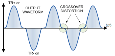
For switch mode AC power sources – aka Class D amplifiers – the biggest contributor to distortion is the cross over distortion that occurs at each voltage zero crossing. Since a switch mode AC source switches its H-bride FETs or IGBT’s between on and off state, there can be no overlap between switching cycles between the positive and the negative half of the H-Bridge. If there was, a direct current path between the positive and negative DC rail of the H-Bridge would be created causing excessive current to flow through power devices. This condition is often called shoot-through and invariably causes the H-Bridge or power amplifier output stage to fail. To prevent this, a certain amount of so called ‘dead-time’ is needed between turning one side of the H bridge off and turning the opposite site on. This dead time causes the output sine wave to stop just short of reaching zero, causing a momentary disruption as the voltage jumps from one side to the other. This necessary phenomenon is called cross over distortion and illustrated in Figure 1. Such a non-linear step in voltage contains a large number of harmonics components, contributing to the overall voltage THD.

Why Does it Matter?
Since a programmable AC power source is used to design, test and verify AC powered products, a highly distorted AC sine wave will negatively impact the unit under test. Even a few percent distortion can affect the load if it is sensitive to higher frequencies can the line frequency. Since the switch mode amplifier dead time is typically fixed, the impact of it will increase as the programmed output frequency is raised as it becomes a larger fraction of the decreasing sine wave period. Thus, all PWM AC power sources have higher distortion specs at higher frequencies. For avionics applications where frequencies can be thousands of Hertz, high levels of THD at such frequencies is typically unacceptable.
Linear AC Power Source
One of the best performing programmable AC power sources are linears. As these are not Class D but rather Class AB amplifiers, they are zero biased and require no dead time. Thus, their distortion specs are significantly lower than those of switch mode (PWM) type power sources.
For example, the table bellows shows the voltage distortion specification for two equivalent power AC power sources, a 115ASX PWM switch mode unit and a 112MX linear unit.

Selecting the best programmable AC power source for your application includes paying attention to voltage distortion specifications.
