What is the difference between Inrush Current and Peak Current?
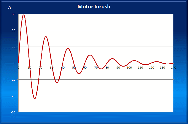
While inrush current has a peak current value, the term “Inrush Current” is commonly used to describe the current that is required to energize an AC powered device or product when first applying voltage and power to it. This is especially true for inductive loads such as transformers, Inductors and electric motors. It also applies to AC/DC power supplies that use a simple rectifier/capacitor input stage. These initial currents can surge and be quite a bit higher than the normal operating current or what is called “steady state” current. An example of an electric motor inrush current is shown in Figure 1. It shows the peak current for the first half cycle as being close to 30 amps and then decaying over subsequent half cycles as the motor spools up.

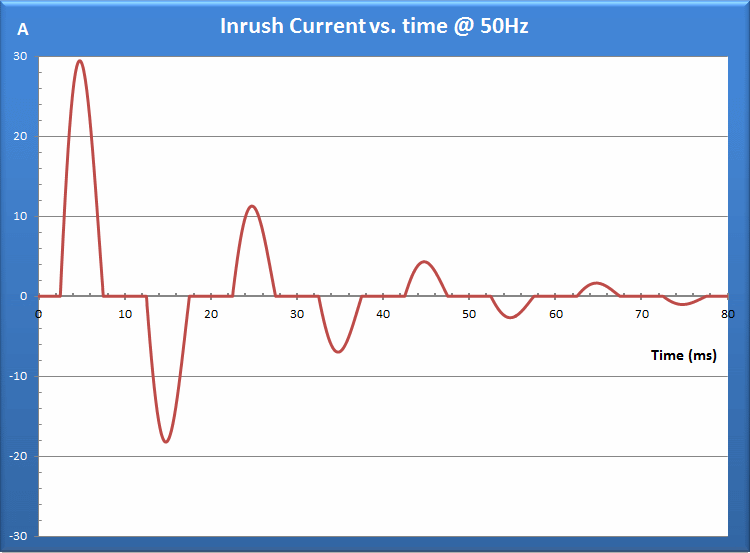
A different example of inrush current is an AC/DC input stage that uses a rectifier, capacitor circuit where the capacitor needs to be charged up to its nominal voltage as shown in Figure 2. In both cases, it is apparent that the inrush current is considerably larger than the steady state current.

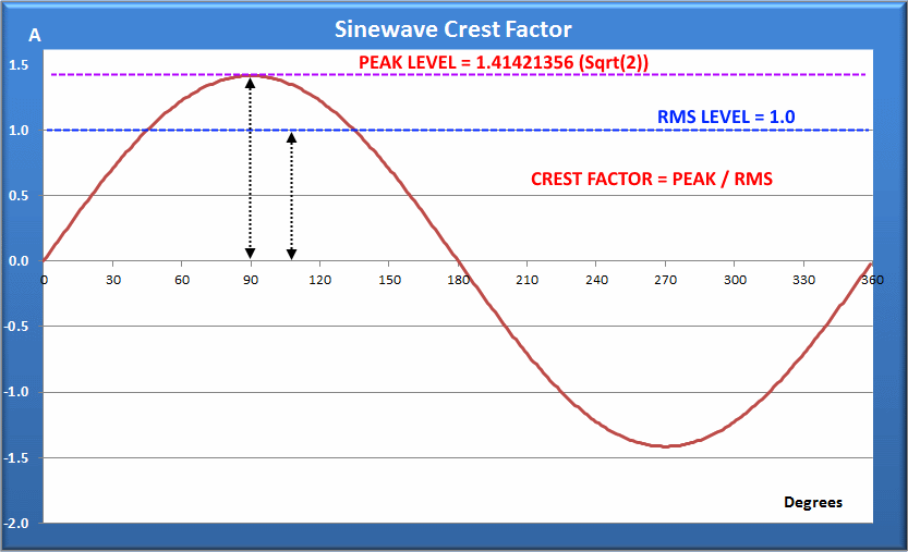
Peak current on the other applies to all AC currents, either inrush or steady state. An AC current waveform has an RMS value representing the effective or DC equivalent current but it also has a peak value, both positive and negative peaks where the current reaches it maximum and minimum value during each cycle. The absolute ratio between the RMS value and the peak value is called crest factor (CF). For a sinusoidal current as encountered with a resistive load, the crest factor will be the square root of 2 or ~1.4142 to 1. This crest factor or ratio is shown in Figure 3.

Other wave forms have different crest factors as shown in Table 1 below for some typical other AC wave forms.

Why Does it Matter?
When using an AC power source to determine the required inrush current for a unit under test, it is important to note that the AC source should be capable of delivering significantly more current for a short period of time than is required to run the unit under test in a steady state condition. In the case of Motors and Inductors, the inrush current can be 10 to 30 times the nominal current. For toroidal inductors, this value may be up to 50 times nominal.
Source current limitation may be both in terms of RMS current rating and peak current rating. For motors and inductor loads, the crest factor of the inrush current is only 1.414 so if the source can support the RMS current, the peak value will be supported as well. For rectified AC input equipment, the current crest factor is generally much higher than 1.414, up to 2 or 3 to 1 so not only the RMS rating but also the peak current rating must be considered. Most available AC power sources will support current crest factors from 2.5 to 4 at max RMS current output.
Current Limiting Effects
If the source is unable to deliver the required inrush current, it may still be used for testing normal operation but the required inrush current cannot be determined as the power source will go into current limit – either RMS or Peak or both – and limit the voltage in doing so. This means the unit under test will typically still start up or turn on but not as fast as it would when operated from the utility.
AC Source Voltage Distortion
High peak currents and distorted current wave forms also impact the AC power source distortion as they work against the output impedance of the power source. The lower the power source’s output impedance, the less this effect will be. Figure 4 shows the effect of highly distorted current on output voltage distortion. As the current reaches its peak near the top of the voltage waveform, the voltage is pulled down causing some flat topping to occur.

To alleviate this effect, a programmable output impedance feature may be offered on some AC source models that allows the output impedance the be reduced.
